Bluetooth Build Button, Part 3: the enclosure rough-ins
With the core idea now functional (Part 2: the proof-of-concept), it’s time to start working on a proper enclosure.
For building models, I’ve been using Autodesk Fusion 360. It’s a powerful parametric modeling tool and has free non-commercial licensing. The license is only one year long, but can be renewed each year.
What is parametric modeling?
Let’s compare direct and parametric modeling software for a minute, because the distinction is important.
A couple years back before I knew the difference, I was working in a direct modeling tool, the now-defunct Autodesk 123D Design (which was a wonderful, simple, intuitive tool, but that’s neither here nor there). I ended up designing the most complex model I’ve built yet – an internet-connected, Raspberry Pi-powered, touchscreen RGB lamp for an Introduction to Connected Devices course at Case Western Reserve University.
It was pretty complex – it was tooless and had an interlocking sliding-rail system for opening and closing, as well as mounting features for the hardware inside:
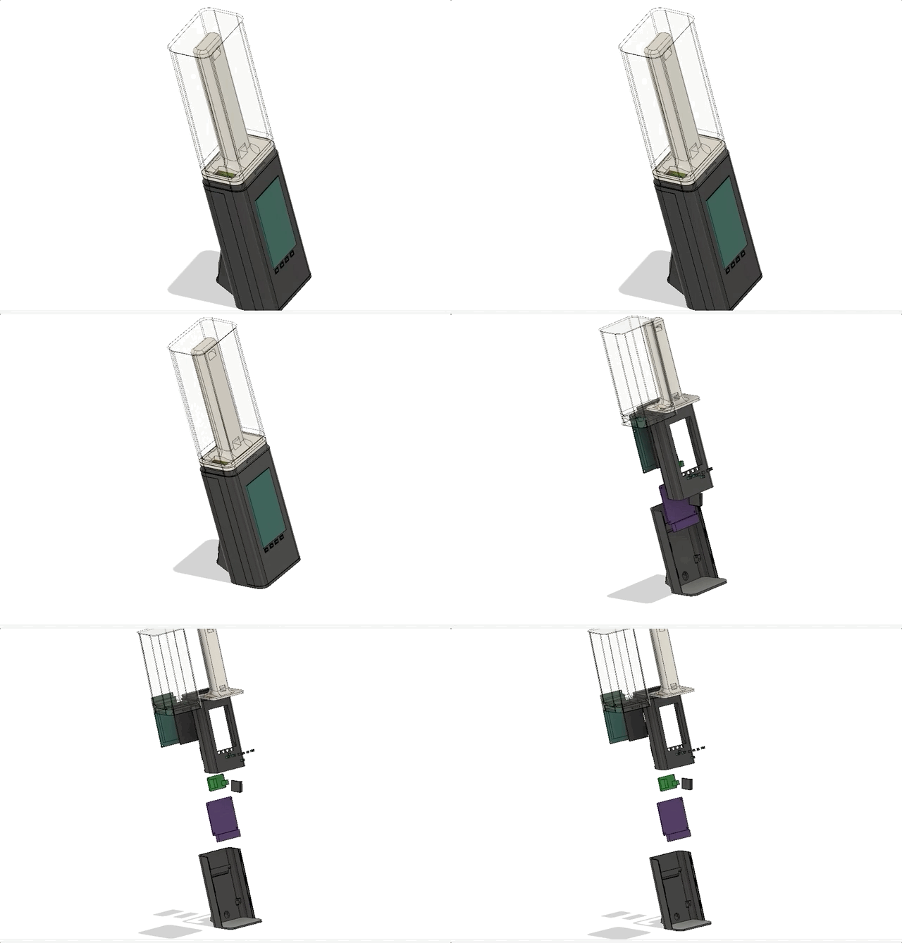
With direct modeling, you’ve got the model you’re working on and … that’s it. If you realize you need to change something simple, shave a millimeter here or there, you’ll probably be fine. If you need to go back and change something fundamental, something that other features of the model are built upon, you’ll need to go back to an older version of the file (you did put the file in version control, right?), make the change, and then manually redo any work that came afterwards – this could be hours of work, and the chance of error is pretty huge.
As you can imagine, this became quickly untenable for changes of any appreciable size. It was pretty humbling to realize how quickly my ignorance of tooling choice turned into something resembling a heap of tech debt.
Direct modeling was a simple, useful tool being abused with a mismatched use case. If you’re modeling anything (mechanical) of complexity you may ever want to change, parametric modeling is the way to go.
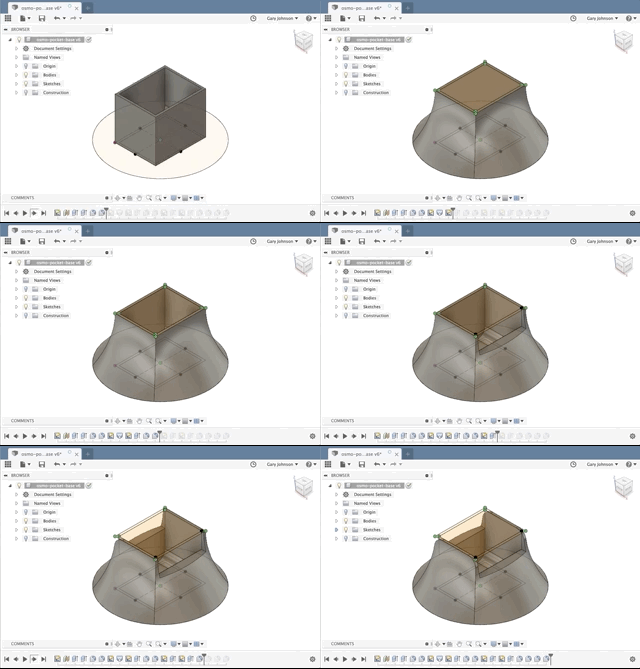
With parametric modeling, your source-of-truth is not the model in front of you – it’s the history of changes you made to get there, and your current model is a byproduct of those changes. Fusion 360 allows you to easily traverse that history:
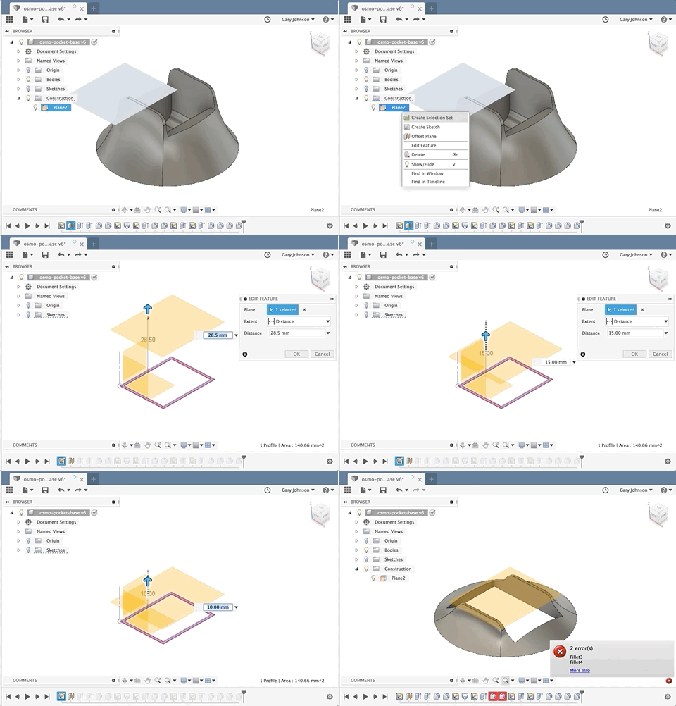
And because of that change in perspective, making fundamental modifications becomes incredibly easy. Think of it like a git rebase – you’re inserting a change earlier in history, and then replaying the rest of the changes on top. When changes aren’t compatible, you even have the opportunity to resolve conflicts:
So, parametric modeling is really powerful and it’s going to allow me to quickly iterate on this enclosure moving forwards.
Gathering parts
When modeling an enclosure, the first thing I do is build rough-ins – replicas of all the parts I’m going to put in the enclosure. They don’t need to be perfect, but should have accurate measurements for any mounting holes, ports, anything where alignment is key.
We’ve got a couple parts to rough-in. The button and contact switch assembly:

One of these batteries – we haven’t figured out how much juice (or room) we need yet:

A power switch:

And the Feather:
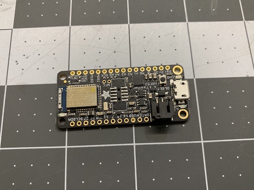
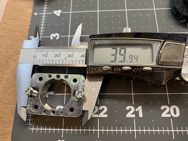
We’ve got to measure all this stuff to actually model it. I recommend using digital calipers for this work:
Modeling the rough-ins
Let’s start with the switch.
When doing parametric modeling in Fusion, you’ll be working a lot with sketches and then extruding them into 3D shapes. Sketches are great because they allow you to define complex layout rules in a 2D space that can react automatically to future modifications.
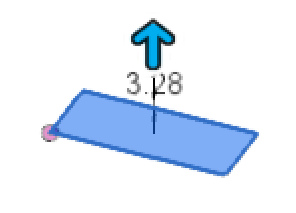
For the switch, we’ll start with a rectangle sketch the width and depth of the switch, and then extrude the height:
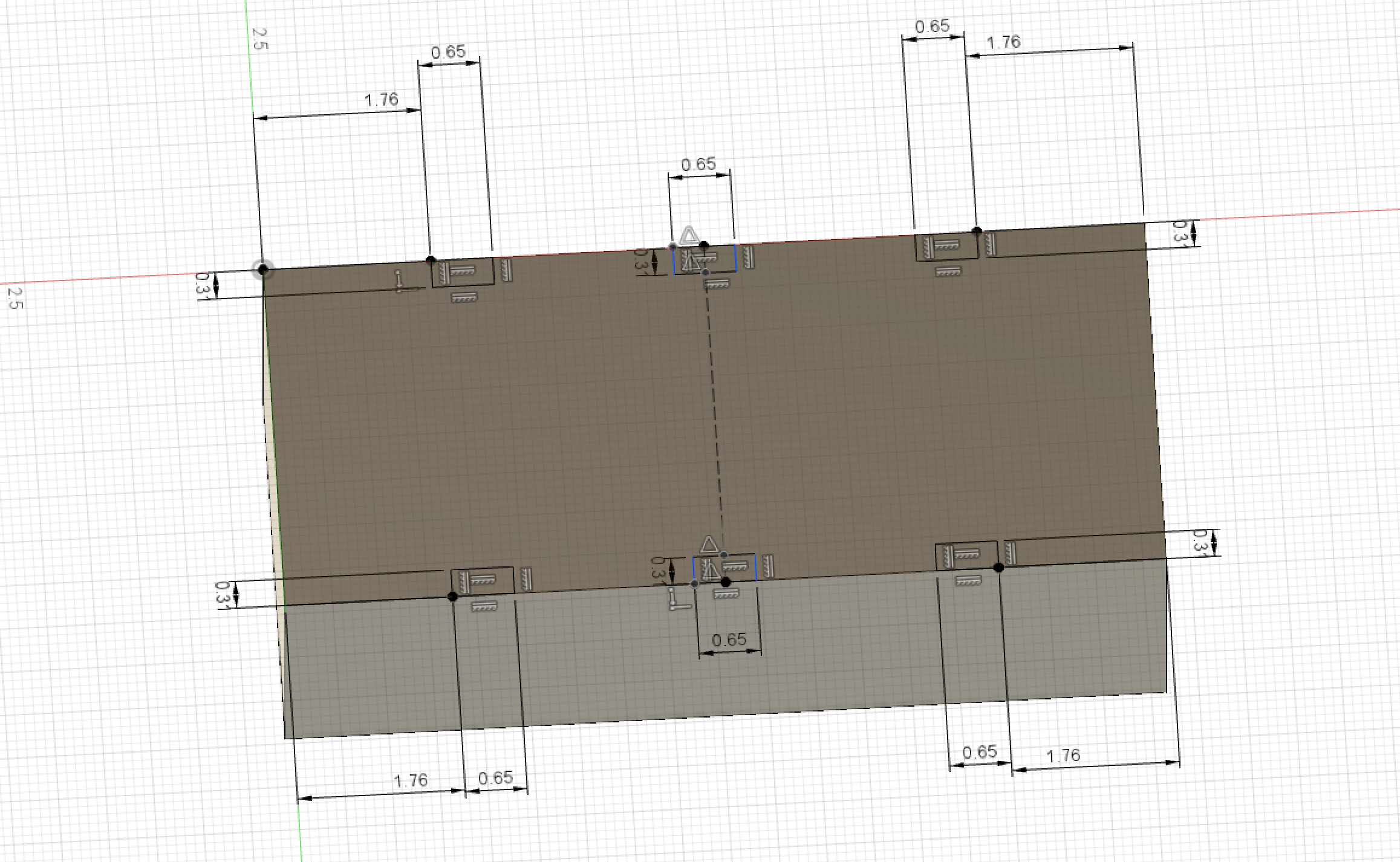
Then we’ll make another sketch on the bottom of our new switch and build a rectangle for each pin:
Extrude those pins, extrude a button, you get the idea. After a few more rectangles and a few more extrusions, we have something resembling a switch.
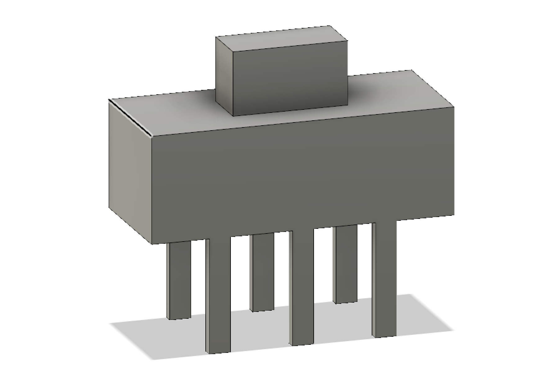
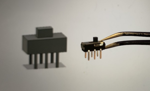
The top of the switch is longer because we’re roughing in the full range of motion of the switch, ensuring when we test for placement, the switch will be able to move back and forth freely.
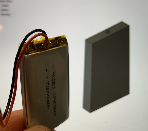
Okay, so I went a little lazy on the battery. LiPo batteries have been known to expand, so I was a little generous with the dimensions, and made a little nub to indicate where the wires exit.
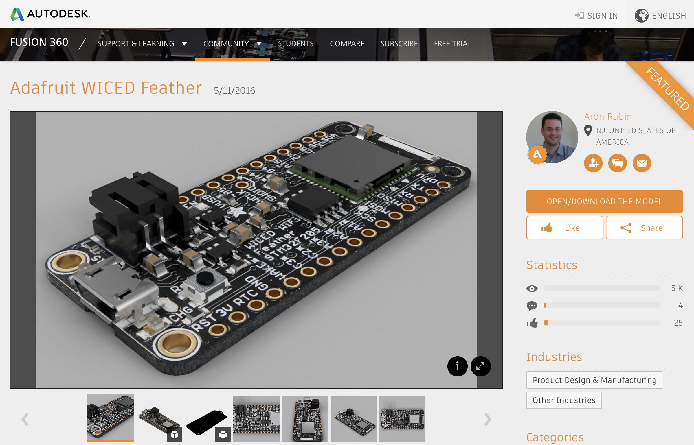
The Adafruit Feather line has standardized ports and mounting holes, so I assumed I would be able to find an existing model of any Feather, and sure enough, I did:
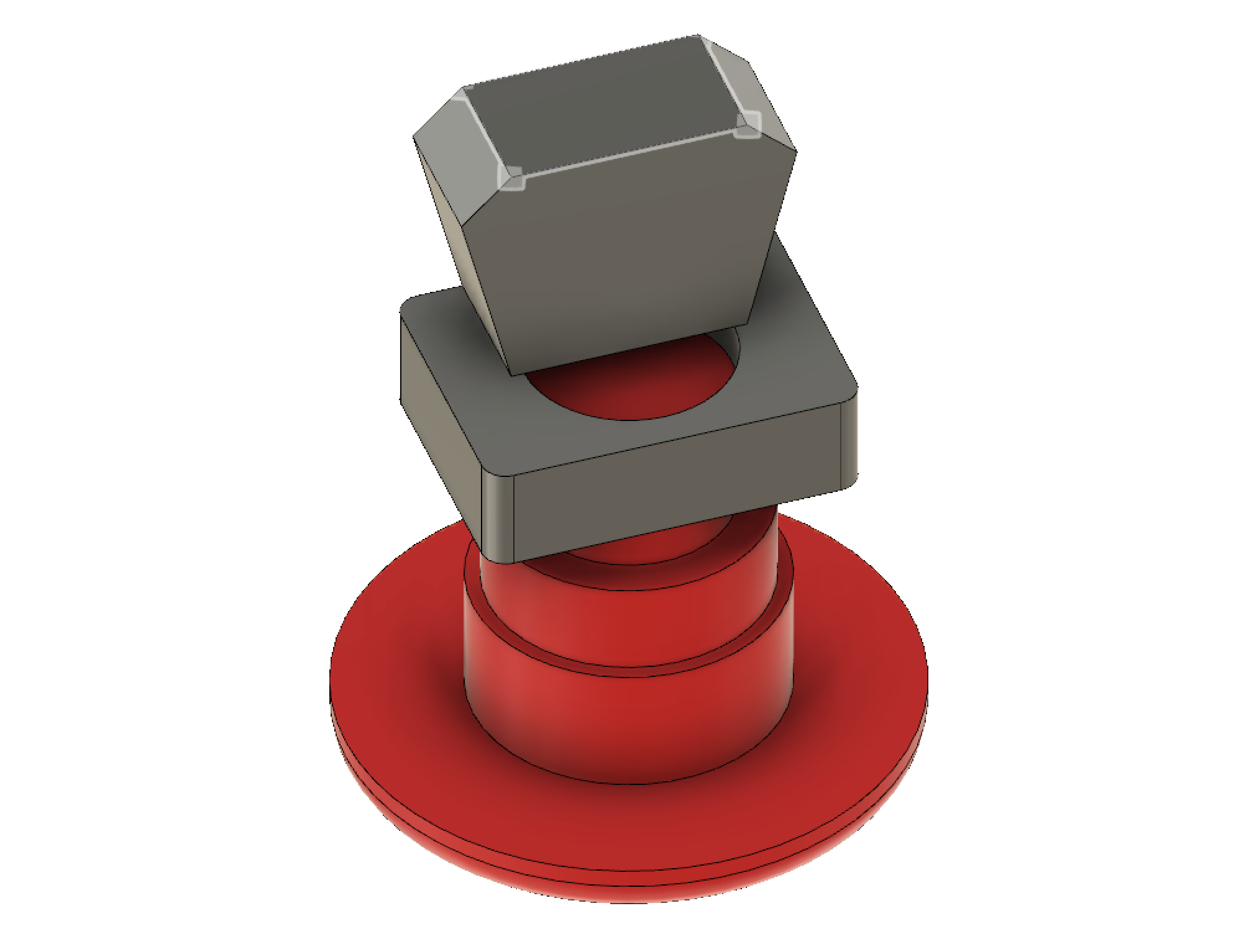
Finally, the button, which I took extra care with, since it has such a big impact on the available space in the enclosure.
Modeling the enclosure
I’d like the enclosure to roughly match the diameter of the button, so let’s just drop this stuff in a cylinder and see how it fares:
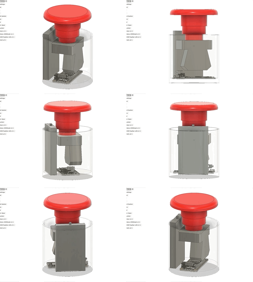
That battery looks like a problem. Additionally, I’d like the top of the enclosure to twist off, which means the button has to be free to twist with it:
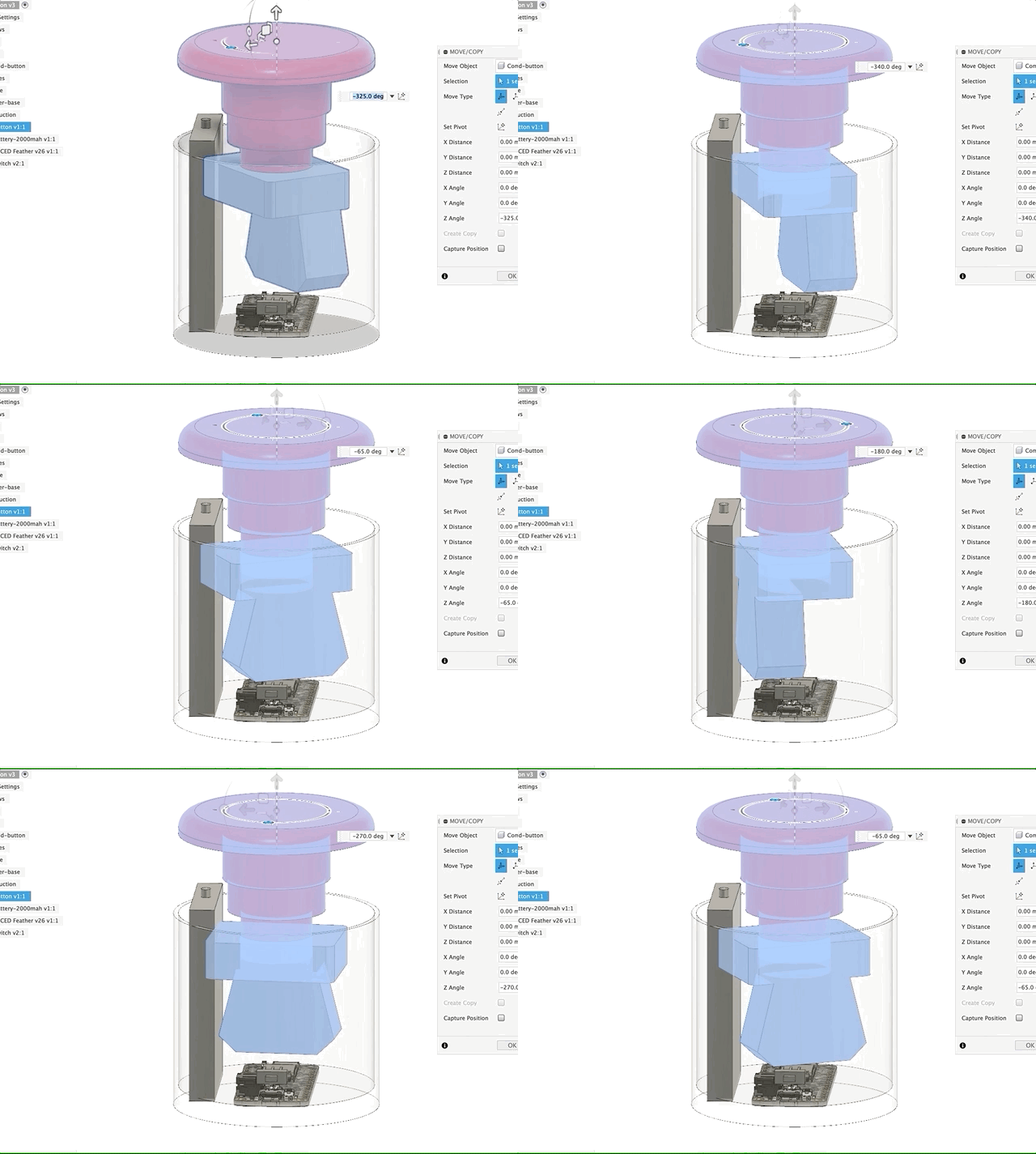
Okay, so we’ll go model the smaller battery and start there. There’s another issue, which is that the USB port and power switch don’t really work with a rounded surface:
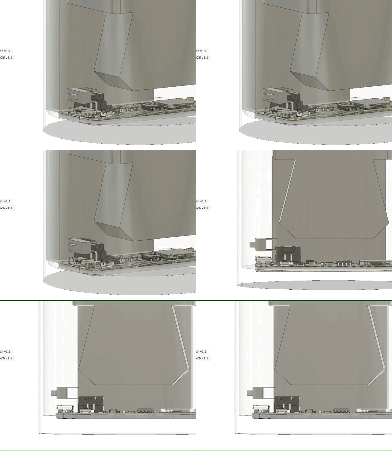
Looks like we’re going to need to build a flat into our cyclinder.
Scope Creep
Finally, the contact switch on the button really takes up a ton of good space – this is something I’d like to address, but it works and building an alternative is going to distract us from delivering V1. Let’s put it on our nice-to-haves list for now.
What’s next
With the rough-ins done, we managed to visualize some potential issues. We’ll move to the smaller battery and then get to work on making a v1 enclosure (Part 4: v1.0 complete) we can 3D print and test out.